Arc Stud Welding Process
Arc Stud Burn Off
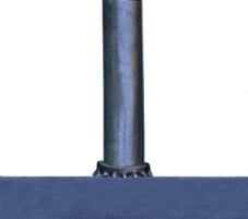
“Burn-off” is the reduction in length of a weld stud, which occurs during the arc stud welding process.
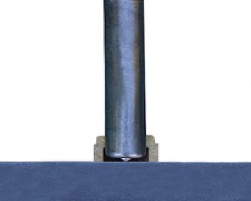
STUDs – Before and after weld:
The Process
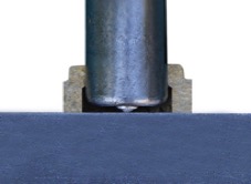
- Place stud & ferrule to work surface.
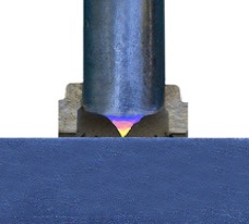
- When the trigger is pulled, the stud lifts, and draws a pilot arc.
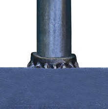
- Pilot arc turns to sustained arc while stud remains lifted
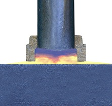
- In a split second the stud plunges to base material, a fillet solidifies around base and the ferrule is removed.
Determining Proper Length Stud – Formula:
(After weld length + “burn off” = Stud Purchase length)
*EXAMPLE of a ¾” x 4.00” Shear Connector welded thru decking:
4.00” (after weld length) + 3/8” (burn off) = ¾ x 4-3/8” (stud purchase length)
Stud Reductions per Diameter:
| Stud Diameter | Approximate Reduction |
|---|---|
| 3/16”-1/2” | 1/8” |
| 5/8”-7/8” | 3/16” |
| 1” and over | 1/4” |
| 3/4″ thru-deck | 3/8” |
Examples of After Weld Lengths Bare Steel vs. Thru Deck:
Example 1
| Approx. after weld length when welding to bare steel. | Approx. after weld length when welding thru metal decking. | |
|---|---|---|
| 4-3/16″ | 4.00″ | 3.813″ |
| 4-3/8″ | 4.188″ | 4.0″ |
| 4-7/8″ | 4.688″ | 4.50″ |
Example 2
| Approx. after weld length when welding to bare steel. | Approx. after weld length when welding thru metal decking. | |
|---|---|---|
| 5-3/16″ | 5.00″ | 5-7/8″ |
| 5-3/8″ | 5.188″ | 5.688″ |
| 5-7/8″ | 5.0″ | 5.50″ |
Drawn Arc Welding
Drawn arc welding is the most commonly used type of arc stud welding and is named so because the stud is drawn or pulled away from the base material as part of the welding process. This allows the stud to plunge into the base material, providing greater force and better penetration.
It also utilizes:
- A ferrule to contain the molten metal around the base of the stud and act as an arc shield and prevents sparks from being disbursed.
- An aluminum flux ball at the tip of the weld stud which when vaporized eliminates the oxygen around the weld area in order to minimize porosity. It also acts as an arc stabilizer.
- Three phase electricity, usually 230, 460 or 575 volts. (Single phase electricity can be used for welding arc studs up to 1/2″ diameter.)
The sequence of drawn ac stud welding is illustrated on the following pages:
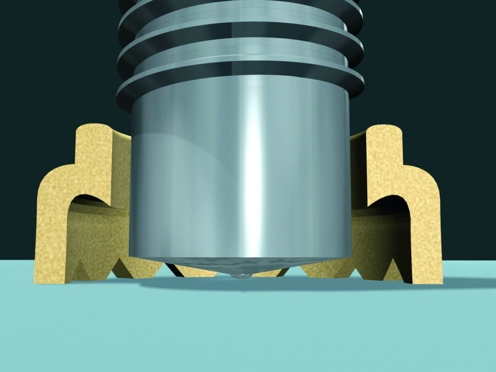
1. The process starts with the stud sitting on the base material with a ferrule around the base of the stud to limit the amount of oxygen entering the weld zone, help form the molten metal and contain the spark (i.e. spark shield).
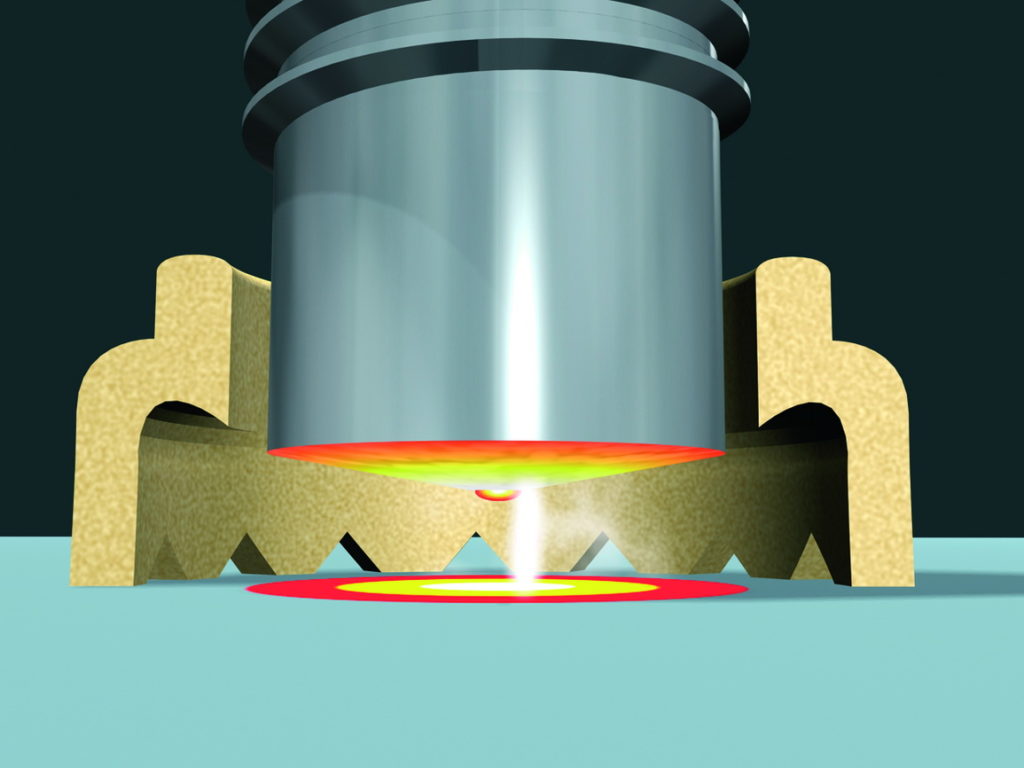
2. The trigger is pulled, the stud lifts and draws a pilot arc. The pilot arc creates a path for the weld arc to follow and vaporizes the flux ball which purifies the weld surface from oxygen in order to minimize porosity in the weld zone.
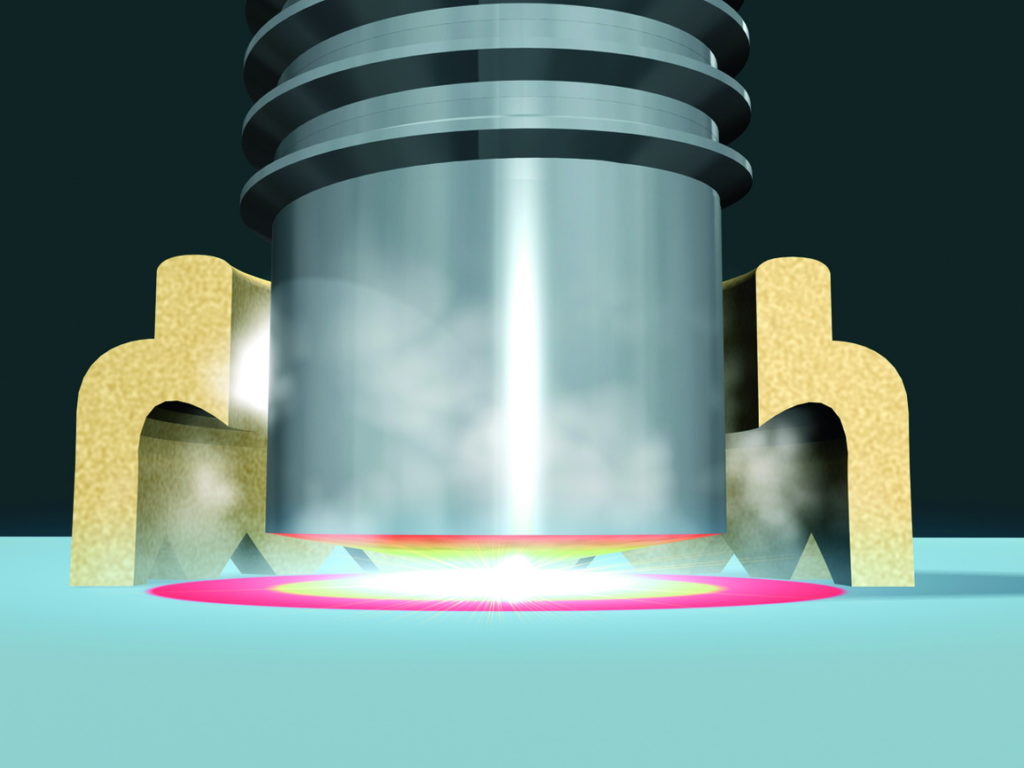
3. When the stud is at its highest point the weld arc is ignited and melts the base of the stud and the base material. After the weld time has elapsed the stud is plunged down into the base material.
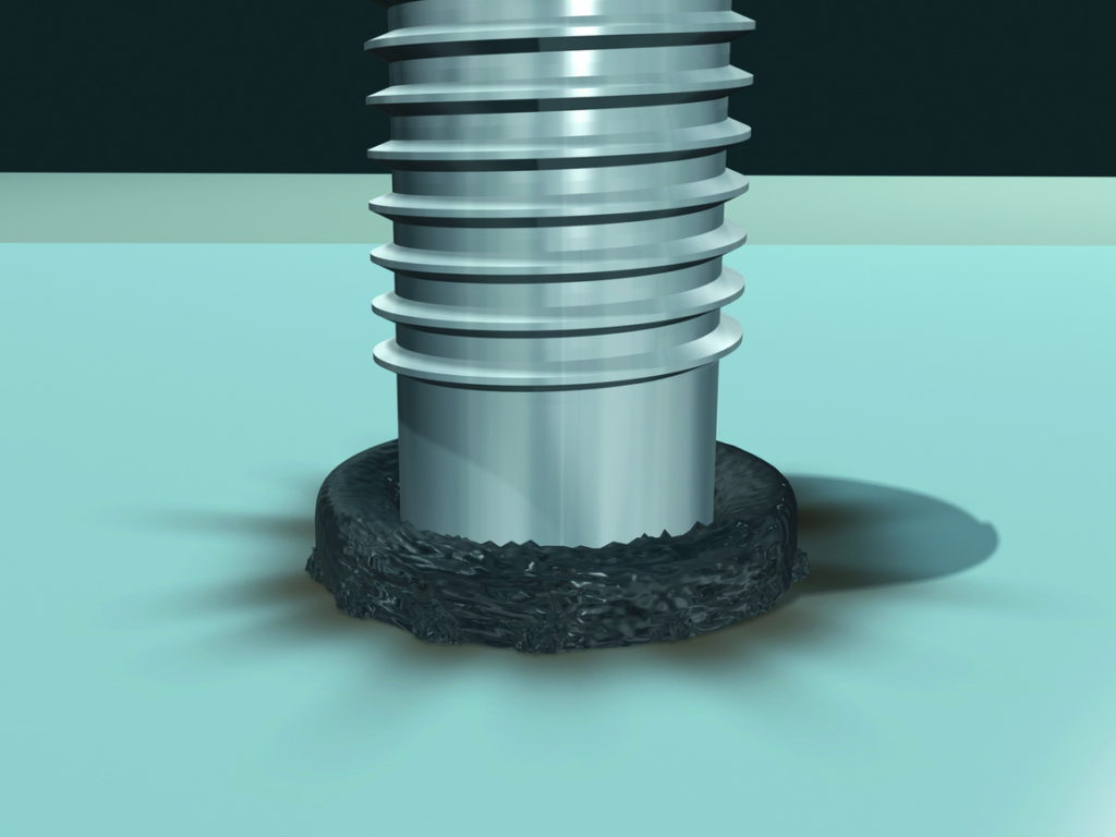
4. The displaced metal forms a fillet around the base of the stud. The entire base of the stud, not just the perimeter is welded to the base material.
In summary, drawn arc stud welding:
- Is usually used on thicker base material and larger diameter studs than capacitor discharge stud welding.
- The stud is drawn away from the base material in the initial stage of the welding process and then plunged into the base material.
- A ceramic ferrule is used as an arc shield and to contain the molten metal.
- An aluminum flux ball at the tip of the stud is used to remove oxygen when vaporized by the pilot arc and also acts as an arc stabilizer.
